Setting Up MikroTik Point-to-Point (PtP) Outdoor Wireless Link: Comprehensive Guide from Hardware to Configuration
Looking to establish a wireless internet/network connection between two buildings or distant points? In this comprehensive guide, understand the necessary hardware for a PtP link using MikroTik devices, learn step-by-step configuration steps, and discover tips for creating a seamless and high-speed connection.
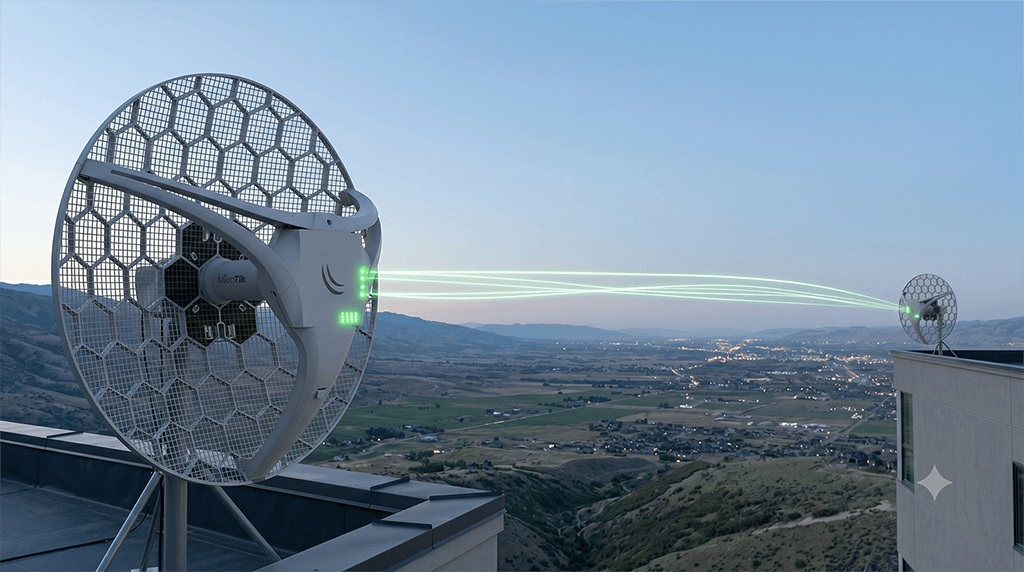
MikroTik offers reliable and powerful solutions for Point-to-Point (PtP) wireless links. Whether you are connecting two offices of your company or extending internet from one point to another, PtP links provide flexibility and performance. However, choosing the right hardware and making the correct configuration is essential for a successful setup. In this post, we will cover the entire process of setting up a MikroTik PtP link in detail, from hardware to software.
1. Essential Hardware Cards and Components for MikroTik PtP Connection
For a flawless wireless connection, not only the routerboard but also the correct antennas and additional components are required. Here are the basic hardware components for a PtP link:
a. Integrated Devices vs. Separate Card/Antenna Solutions: MikroTik offers both integrated (antenna and radio in one) and separate routerboard/antenna solutions for PtP links.
- Integrated Devices (e.g., SXTsq, LHG, QRT): Easier to install, require fewer pigtail connections, and are generally more weather-resistant. Ideal for beginner and intermediate applications.
- Separate Cards and Antennas (e.g., RB912, RB922 + Directional Antenna): Offers more flexibility. Performance can be significantly enhanced over much longer distances by using very high-gain, narrow-beam antennas. However, there are pigtail losses and additional mounting complexity.
b. Antennas: To establish direct communication between two distant points, directional antennas (panel, dish, grid) must be used.
- Antenna Type: For PtP, directional antennas are preferred. While panel antennas have a wider beamwidth, dish antennas are much narrower-beam and higher-gain (ideal for long distances).
- Gain (dBi): Indicates how much the antenna focuses and amplifies the signal. As the distance increases, higher-gain antennas are required.
- Frequency Band: Ensure your antenna and wireless card operate on the same frequency (typically 2.4 GHz or 5 GHz, sometimes 60 GHz). 5 GHz usually offers less congestion and higher speed.
c. Wireless Cards (if not integrated): The frequency range, power output, and connector types of the wireless cards you plug into your routerboard are important.
- MikroTik Card Models: Cards like R11e-2HnD (2.4 GHz), R11e-5HnD (5 GHz) can be installed in routerboards. Higher-power cards can provide longer range.
- Connectors: The antenna connector type on the card (e.g., MMCX, U.FL) and the antenna pigtail connectors must be compatible with each other.
d. Pigtail Cables and Adapters: Used to connect the wireless card to the antenna. High-quality and short cables should be preferred to minimize signal loss.
e. Mounting and Protection:
- Outdoor Enclosure: Use durable enclosures that protect your devices from weather conditions (integrated devices are already protected).
- Grounding: Be sure to perform proper grounding to protect outdoor devices and antennas from overvoltages such as lightning strikes.
- PoE (Power over Ethernet): Use PoE injectors and cables to transmit both electricity and data to the devices. Prefer high-quality outdoor Ethernet cables.
Summary: For a PtP link, either choose an integrated solution (like SXT, LHG) or combine routerboard, wireless card, directional antenna, pigtail, and protective equipment. In either case, pay attention to frequency compatibility, antenna gain, and grounding.
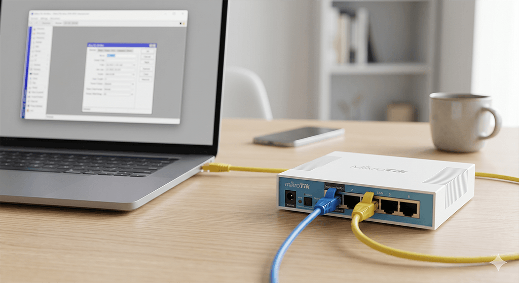
2. MikroTik PtP Link Setup Steps (via WinBox)
Now, after obtaining the hardware, let’s move on to the installation phase. In this example, we will configure two MikroTik LHG5 devices as a transparent bridge. One device will operate in AP Bridge mode, and the other in Station Bridge mode.
A. Main Station (AP) Configuration (Device at the main point)
-
Connecting via WinBox: Connect your computer and the LHG5 device over Ethernet. Open WinBox, click on the device’s MAC address from the Neighbors tab, and log in with the default username (
admin) and password (blank or on the label). -
Security: First, set the admin password from the System > Password menu.
-
Creating a Bridge: To set up a transparent bridge, we will combine the wireless and Ethernet interfaces.
- Click on Bridge from the menu.
- Press the
+button, leaveName: bridge1as it is, and clickOK.
-
Adding Interfaces to the Bridge:
- Switch to the Ports tab in the same window.
- Click the
+button, ensureInterface: ether1andBridge: bridge1are selected, and clickOK. - Click the
+button again, ensureInterface: wlan1(or your wireless interface) andBridge: bridge1are selected, and clickOK. Now, the wireless and Ethernet interfaces are transparently connected to each other.
-
Wireless Configuration:
- Click on Wireless from the menu.
- Double-click on the
wlan1interface. - Go to the Wireless tab.
- Mode: Select
ap bridge(this device will be the main transmitter). - Band: For 5 GHz AC devices, you can choose
5GHz-only-Nor5GHz-A/N/AC. For other compatibilities, choose bands like2GHz-b/g/nor5GHz-a/n. - SSID: Determine the connection name (e.g.,
PtP_Link_Main). - Frequency: It is important to choose a clean frequency. Scan the surrounding frequencies with the
Scanbutton and manually select the emptiest one, or you can leave it onauto(manual gives more control). - Security Profile: Press the
+button to add a encryption profile (or edit the default profile). CheckMode: dynamic keys,Authentication Types: WPA2 PSK,Unicast Ciphers/Group Ciphers: aes-ccm. Type a strong password in theWPA2 Pre-Shared Keysection and clickOK. - Select the profile you created as the
Security Profileon the main Wireless tab. - In the
Channel Widthsection, you can select20MHzor40MHz,80MHzdepending on speed requirements (wider channel, higher speed but more pollution sensitivity). - Click
OKto save.
-
Assigning Management IP:
- Go to the IP > Addresses menu.
- Click the
+icon. - Type
192.168.88.1/24(or any management IP you desire, can be on the same subnet as your main network). - Select
Interface: bridge1and clickOK.
B. Client Station (Station) Configuration (Device at the distant point)
To configure the other LHG5 device at the distant point, repeat most of the steps above, but the wireless mode will be different:
-
WinBox Connection & Password: Connect to the device and set a password.
-
Creating a Bridge: Create a new bridge named
bridge1from the Bridge window. -
Adding Interfaces to the Bridge: Add
ether1andwlan1(or relevant wireless interface) interfaces tobridge1from thePortstab. -
Wireless Configuration:
- Double-click
wlan1from theWirelessmenu. - Go to the Wireless tab.
- Mode: Select
station bridge(this device will connect to the AP Bridge). This mode provides a transparent bridge when combined with a bridge. - Band, SSID, Frequency: Enter the exact same values you determined on the main station. (SSID:
PtP_Link_Main, Frequency: The frequency you chose). - Security Profile: Create the exact same security profile as on the main station or edit the default one and enter the same password. Then, select this profile on the main Wireless tab.
- Click the
Scanbutton to perform a scan. When you see the main station’s SSID, click on it and sayConnect. If frequency and password are correct, it will connect shortly. - Click
OKto save.
- Double-click
-
Assigning Management IP:
- Go to the IP > Addresses menu.
- Click the
+icon. - Type
192.168.88.2/24(different management IP from the main station but same subnet, any IP you desire). - Select
Interface: bridge1and clickOK.
3. Antenna Alignment and Testing
After the configuration is complete, physically aligning the antennas is very important.
- Physical Alignment: Roughly align the devices to face each other.
- Alignment Tools:
- MikroTik Alignment Tool: Double-click the interface in the Wireless menu and go to the
Statustab. Here you can see values like signal strength (Tx/Rx Signal Strength), CCQ (Signal Quality). - Built-in LEDs: Many integrated MikroTik devices have LEDs that show signal strength. Try to increase the number of LEDs on the back of the device.
- MikroTik Alignment Tool: Double-click the interface in the Wireless menu and go to the
- Fine Tuning: Slowly move the antenna on one side on the horizontal and vertical axes. Let the other person follow whether the signal strength increases or decreases (or you follow via WinBox). The lower the signal strength (e.g., -50 dBm, -60 dBm, better than -80 dBm), the stronger the connection. The CCQ value should be as close to 100% as possible.
- Adjusting Both Sides: After aligning one side, finely align the device on the other side as well. Try to capture the best signal values.
- Connection Test: After the devices are connected,
pingfrom one station to the other. Ensure ping times are low and lossless. You can also test connection speed and throughput values using theTools > Bandwidth Testtool.
Conclusion
By selecting the correct hardware and following these steps, you can establish uninterrupted and high-performance Point-to-Point outdoor wireless connections with MikroTik devices. Remember, antenna gain, frequency selection, grounding, and meticulous antenna alignment are key to a successful PtP link. Thanks to the transparent bridge structure, you can gain flexibility by merging your main network and distant network as if they were a single network.
Visit the store to browse and purchase wifiAnten products.
Enter storeQuestions
No questions yet. Be the first to ask.

Written by
wifiAnten Ekibi
wifiAnten içerik ekibi.
Table of Contents
Related Posts
My First MikroTik Configuration: Basic Setup Guide for Beginners
Meeting your MikroTik router for the first time? Don't be intimidated! In this guide, learn step-by-step how to configure your first MikroTik settings, from connecting via WinBox to setting up basic network parameters and getting internet access.

How to Prevent MikroTik Brute Force and Port Scanner Attacks?
In this article, we explain with examples how preventive measures can be taken against brute force attacks using MikroTik devices.

What Information Is Needed to Build a Wireless Infrastructure for an Outdoor Camera Project?
To build a reliable wireless infrastructure for outdoor camera projects, key details such as camera locations, distances, line of sight, power availability, PoE requirements, antenna type, frequency band, network topology, recording center, and environmental conditions must be analyzed correctly. In this guide, we explain the essential data needed for planning outdoor IP camera wireless connections.